 +86 15338350382
 日本語
日本語 英語
英語 スペイン語
スペイン語 フランス語
フランス語 ロシア
ロシア イタリア語
イタリア語 ドイツ語
ドイツ語
 10 分間で読める発表 Dec 15 2025
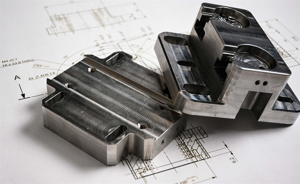
CNC加工のための技術図の準備は,製造プロセスの重要なステップです.精密な部品や部品を作成するために機械工具を導くブループリントとして機能します.このタスクに着手するとき,CNC加工プロジェクトの正確性,効率,成功を確保するために,注意する必要があるいくつかの重要な側面があります.
CNC加工のための技術図を準備する際,正確さ,効率,安全性を確保するためにプロセスに関連する複雑さを理解することが重要です.CNC加工は,部品や部品を生産するために詳細で正確な図面に大きく依存する高精度な製造方法です.このガイドでは,CNC加工のための技術図を準備する際に知る必要があるものの包括的な概要を提供し,基本的なコンセプト,ベストプラクティス,避けるべき一般的なこのこの避難点をカバーします.
CNC加工の基礎を理解する
技術図の重要性
技術図はあらゆる製造プロセスのブループリントであり,CNC加工において特に重要です.これらの図は,材料を形作り,切り,組み立てる方法について,機械に正確な指示を提供します.詳細な寸法,製造プロセス全体を指導する材料仕様,その他の不可欠な情報が含まれています.
技術図の種類
CNC加工で使用される様々なタイプの技術図があります:
● 正字ビュー:これらの図は、正面、上部、側面から見られているようなオブジェクトを表しています。それらは部品の形状とサイズを理解するために不可欠です。
● セクションビュー:これらの図は,部品の内部構造を示し,複雑な几何学と組み立てを明確にするのに役立ちます.
● 詳細図:これらの図は,部品の特定の領域に焦点を当てており,本本線,穴,表面などの特徴に関する追加情報を提供します.
● 組立図:これらの図は,複数の部品が完全な組み立てを形成する方法を示しています.
CNC加工に含まれる主要な要素
寸法と公差
寸法はオブジェクトのサイズの測定であり、公差は名称寸法からの受け入れ可能な変化範囲を指定します。CNC加工では,正確な寸法と厳しい部部部品が正しく一緒に合わせ,意図通りに機能することを確保するために非常に重要です.
● サイメンションの条約:尺寸を示すためにリーダーラインと矢印を使用し,混乱を避けるためにビューエリアの外部に尺寸を置くなどの標準的な尺寸調整規則に従います.
● 許容地帯:各次元の許容区域を明確に示します。これは,機械師が指定された測定にどれだけ緊密に従うかを理解するのに役立ちます.
コンベンションとシンボルを描く
技術図は,情報を効率的に伝達するために一連の規約とシンボルを使用します.次のことを知ってください:
● ラインと矢印:これらは寸法,切断面,その他の重要な特徴を示します.
● ハッチングおよびクロスハッチング:これらのパターンは,異なる材料を表すか,木製物体の木木の方向を示すために使用されます.
● ピクトグラムと略:これらは複雑な情報を簡単にし、理解が容易になります。
材料と仕上げ
正しい材料と仕上げを指定することは,終製品の機能と外観に不可欠です.
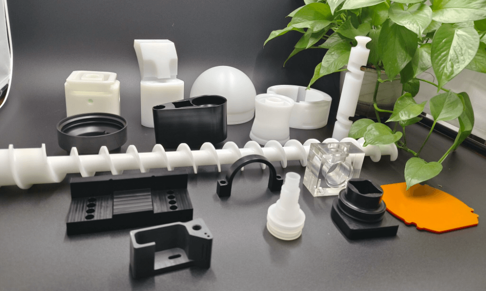
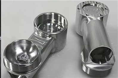
● 材料の選択:強度、耐久性、加工性などの部品の機能要件を満たす材料を選択します。一般的な材料には、アルミニウム、鋼鉄、チタンなどの金属、ナイロンやアクリルなどのプラスチックが含まれています。
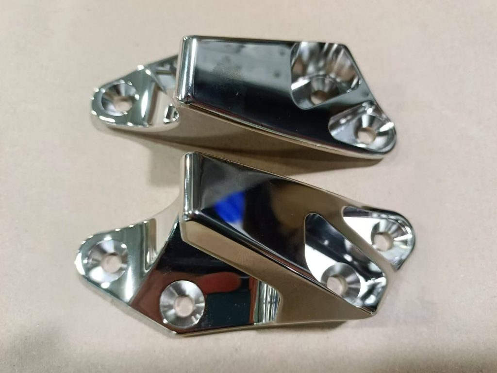
● 表面の仕上げ:磨き,マット,またはテクスチャーの表面など,望ましい表面の仕上げを指定します.これは、部品の美学、機能性、耐磨性および腐食性に影響を与える。
公差と精度
プロジェクトの公差と精度要件を決定します.公差は寸法やその他の特徴の受け入れ可能な変化を指し,精度は望ましい値に近い程度を指します.
● 次元の許容:各次元の受け入れ可能な範囲を指定します。
● 幾何学的公差:形状と方向における許可される偏差を定義します。
● 表面の仕上げ:望ましい表面の粗さや質感を指定します。
幾何学的寸法と公差
Geometric Dimensions and Tolerances(GD&T)は、技術図の幾何学的特性と公差を定義し、伝達するために使用されるシステムです。部品が正しい形状,サイズ,方向に製造されていることを確保するのに役立ちます.
● シンボルと記号:平行性、垂直性、同心性などの GD&T シンボルや記号に精通します。これらのシンボルは,製造プロセスに対する追加の精度と制御を提供します.
● 日付参照フレーム:データ参照フレームを使用して,幾何学的特徴を測定するための一致的で繰り返し可能な基礎を確立します.
CNC加工における詳細な考慮
特徴と加工操作
穴,ポケット,スロット,機機械化する必要があるすべての特徴を特定し,明確に示します.
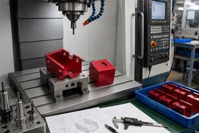
● 加工操作:フライス(複雑な形状や特徴に使用される)、掘削(穴を作成するために使用される)、回転(必要必要必要な加工作業)、磨削(滑らかな表面の仕上げを達成するために使用される)などの必要な加工作業を指定します。これは,機械師が操作の順序を理解し,製造プロセスを計画するのに役立ちます.
● ツールパス:いくつかの場合,工具のパス情報を含むことは,機械師に部品を効率的に加工する方法を指導するのに役立つかもしれません.
注解とメモ
注解やメモは,あなたの部品にとって非常に重要な意味を持つ追加情報を提供します.これには以下が含まれています:
● 材料ノート:材料および特別な要件を指定します。
● 加工メモ:加工プロセスと操作に関する情報を提供します。
● 表面の仕上げのノート:望ましい表面の仕上げと関連する指示を指定します。
● 一般的なメモ:機械師に役立つかもしれない他の関連情報を含む。
組み立ておよび組み立て情報
技術図に組み立てが含まれている場合は,部品がどのように合わせるかについて明確な情報を提供します.
● アセンブリシーケンス:組み立てシーケンスを概要にし,初に組み立てるべき部品と,それらをどのように整列するべきかを示します.
● フィットアップ公差:部品が正しく一緒に合わせ,意図通り機能することを確認するために,フィットアップ適適容を指定します.
技術図面の準備のためのベストプラクティス
図面を適切なフォーマットに変換する
図面をCNC機械のソフトウェアと互換性のある形式で保存します。一般的なフォーマットには:
● DWG/DXF:AutoCADおよび他のCADソフトウェアによって使用されます。
● IGES/ステップ:3Dモデルと異なるCADシステム間の相互運用性に使用されます。
● STL:3D印刷およびいくつかのCNC加工アプリケーションに使用されます。
CADソフトウェアの使用
コンピュータ支援設計 (CAD) ソフトウェアは,技術図を作成するための強力なツールです.簡単に共有し,変更できる,正確でスケーラブル,編集可能な図面を作成できます.
● 適切なCADソフトウェアを選択します。SolidWorksのようなプロフェッショナルグレードのソフトウェアであれ、AutoCADのようなよりアクセス可能なオプションであれ、あなたのニーズを満たすCADソフトウェアを選択します。
● CADの特徴を利用します:レイヤリング,サイメンシングツール,レンダリング機能などのCADソフトウェアの機能に慣れてください.これらの機能は,より正確で詳細な図面を作成するのに役立ちます.
業界基準に従う
業界標準に従うことで,技術的な図面が一致し,理解可能で,他の専門家によって作成された図面と交換可能であることを保証します.
● ISO規格:技術図に関する国際標準化機構 (ISO) の規格に従い,ライン規約に関するISO 128-1,幾何学的寸法およびISO 13715などに従います.
● ANSI規格:米国では,ANSI Y14.5Mなどの技術図面の標準に従って,幾何学的寸法と米米米国標準研究所 (ANSI) の標準に従います.
明確で簡単な記号を使う
技術図は,特定の製造プロセスに精通していない人でも,簡単に理解できますべきです.
● 不明確性を避ける:明確で正確な記号を使用して,不明確さや混乱を避ける.たとえば、次元を明確に示すためにリーダーラインと矢印を使用し、幾何学的特徴のために一致したシンボルと記号を使用します。
● 伝説と呼び出しを使用する:図面で使用されたシンボルや略語を説明するための伝説と呼び出しを含む。これは,専門知識のレベルにかかわらず,すべての人が図面を理解できるようにするのに役立ちます.
CNC加工で避けるべき一般的な通りのCNC加工
許容を見過ごす
許容を指定することを無視することは,相互交換できない部品または正しく一緒に合わない部品につながる可能性があります.
● 具体的に:常に重要な寸法に対する公差を指定します。受け入れ可能な変化範囲を示すためにプラス/マイナス記号を使用します。
● フィットと機能を考えてください:許容を指定する際には、部品の適合と機能を考慮してください。重要な特徴にはより厳しい許容が必要かもしれないが、より軽い許容は不重要な領域で受け入れられるかもしれない。
幾何学的特徴を無視する
幾何学的特性を指定しないと,正しい形状や方向に製造されていない部品が生じることがあります.
● GD&Tシンボルを使用します:GD&Tシンボルを使用して平行性,垂直性,同心性などの幾何学的特性を指定します.これは,部品が正しい形と方向に製造されていることを確保するのに役立ちます.
● 一贯してください:一致したデータ参照フレームを使用して,幾何学的特徴を測定するための繰り返し可能な基礎を確立します.これは,部品が毎回同じ仕様に製造されていることを確保するのに役立ちます.
アセンブリ情報を省略
組み立て情報を省略することは,製造プロセス中に混乱やエラーを引き起こす可能性があります.
● 明確な組み立て指示を提供して下さい:組み立てシーケンスを概要にし,初に組み立てるべき部品と,それらをどのように整列するべきかを示します.必要に応じてアセンブリプロセスを明確にするために爆発ビューを使用します。
● フィットアップ公差を含む:部品が正しく一緒に合わせ,意図通り機能することを確認するために,フィットアップ適適容を指定します.これは,組み立てエラーを避け,終製品が仕様を満たすことを保証します.
材料の特性を無視する
材料の特性を考慮しないと,意図された適用に適していない部品につながる可能性があります.
● 材料の特性を理解する:あなたが使用している材料の特性、例えば強さ、加工性、耐腐食性を知ることができます。これにより、仕事に適した材料を選ぶことができます。
● 材料の指定を指定して下さい:グレード,合金,熱処理を含む材料仕様を明確に指定します.これは、製造中に正しい材料が使用されていることを確認するのに役立ちます。
カスタム製造はこれほど簡単ではありませんでした、それは現代製造の中心です。 これほどアクセス可能、正確、または適応可能ではありませんでした。私たちが利用できる技術は、可能性を再定義し、個人や企業がビジョンと完全に一致するカスタマイズされた製品を作ることができます。ユニークな作品や小規模な生産にかかわらず、カスタム製造の柔軟性と効率性は、あらゆる産業にとって強力なツールになります。


 sophia@alcrocn.com
 86 15338350382
 中国広東省東莞市長安鎮の一時帰休コミュニティ北六街。
