 +86 15338350382
 English
 Spanish
 French
 Russian
 Italian
 German
 Japanese
 15 min readPublished Dec 08 2025
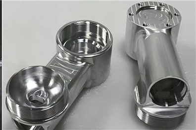
Computer Numerical Control (CNC) machining is a manufacturing process where pre-programmed software dictates the movement of factory tools and machinery. This method is widely used in industries requiring high precision and repeatability, such as aerospace, automotive, and medical device manufacturing. CNC machining enables the efficient production of complex parts with tight tolerances.
What Is CNC Machining?
CNC machining involves the use of computerized controls to operate and manipulate machine and cutting tools. It encompasses various processes like milling, turning, drilling, and grinding. The CNC system interprets a CAD model and translates it into a set of commands that the machine can execute. Key benefits include high accuracy, repeatability, and the ability to work with a wide range of materials.
Main CNC Machining Processes
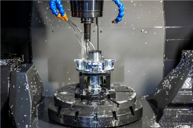
This involves using rotary cutters to remove material from a fixed workpiece. Milling is ideal for creating complex geometries, slots, and holes in both two and three dimensions.
The workpiece rotates while a cutting tool removes material. This method is especially useful for cylindrical parts such as shafts and bushings.
CNC Drilling
Uses drill bits to create precise, repeatable holes. Modern CNC drills can adjust speeds and feeds dynamically based on material and depth.
Electrical Discharge Machining (EDM)
Instead of cutting, EDM uses electrical sparks to shape hard or intricate parts, especially those difficult to machine mechanically.
CNC Grinding
Used to achieve extremely fine finishes or tight dimensional tolerances, grinding is often used as a finishing process.
Benefits of CNC Machining
Unmatched Precision
CNC machines can work within tolerances as tight as ±0.001 inches or better, making them ideal for high-precision applications like aerospace and medical devices.
High Repeatability
Once a part program is perfected, it can be reused to manufacture identical parts with minimal variation — critical for both quality control and scalability.
Material Versatility
CNC machines can cut virtually any solid material, including aluminum, titanium, stainless steel, plastics (like Delrin and PEEK), and even composites.
Fast Turnaround
For both prototyping and production runs, CNC machining offers relatively short lead times, especially when compared to injection molding or casting that require tooling.
Design Complexity
3D tool paths allow CNC machines to craft intricate, detailed parts that would be impossible with manual machining.
CNC vs. Other Manufacturing Methods
| Feature | CNC Machining | 3D Printing | Injection Molding |
|
Material Range |
Wide (metals/plastics) |
Mostly plastics/resin |
Mostly plastics |
|
Strength |
Very High |
Moderat |
High (after tooling) |
|
Tolerance |
Excellent |
Moderat |
Excellent |
| Feature | CNC Machining | 3D Printing | Injection Molding |
|
Setup Cost |
Moderate |
Low |
Very High |
|
Unit Cost (High Vol.) |
Moderate to Low |
High |
Very Low |
|
Speed (Small Batch) |
Fast |
Slow |
Fast (after tooling) |
CNC Manufacturing Standards
General Manufacturing Standards
CNC machining must comply with standardized procedures that guarantee quality, repeatability, and safety. These standards govern everything from the accuracy of machine tools to the traceability of raw materials. Major international bodies include:
· ISO (International Organization for Standardization) – e.g., ISO 2768 for general tolerances, ISO 9001 for quality management systems.
· ASME (American Society of Mechanical Engineers) – e.g., ASME Y14.5 for GD&T (Geometric Dimensioning and Tolerancing).
· DIN (Deutsches Institut für Normung) – widely referenced in European manufacturing standards.
Manufacturers are expected to maintain strict process controls including machine calibration schedules, documented inspection procedures, and operator certifications.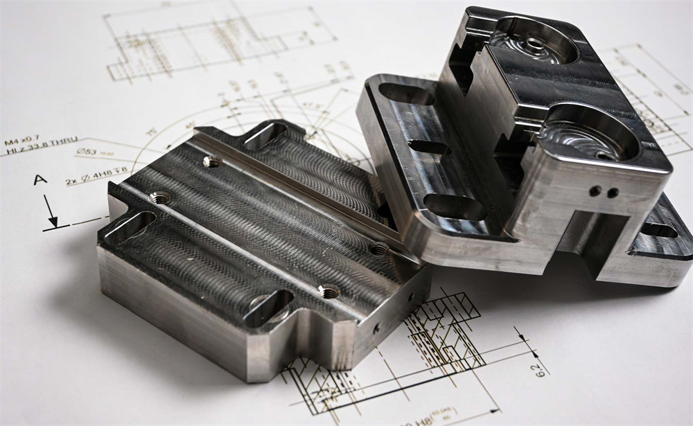
General Tolerances
General tolerances apply when specific tolerance limits are not given in the technical drawings. These are usually based on ISO 2768-m (medium) or ISO 2768-f (fine) standards, depending on part requirements. Typical tolerances include:
· Linear Dimensions: ±0.1 mm to ±0.3 mm
· Hole Diameters: ±0.05 mm to ±0.2 mm
· Angular Tolerances: ±1° to ±3°
General tolerances are suitable for non-critical parts where form, fit, or function is not compromised by minor deviations.
Tight Tolerances
High-precision parts demand tight tolerances, generally defined as ±0.01 mm or better. These tolerances are common in aerospace, defense, and precision instrumentation. Meeting such tolerances requires:
· High-stiffness CNC machines with thermal stability
· Climate-controlled machining environments
· Tool compensation and in-process measurement systems
· Advanced cutting tools with minimal deflection
Keep in mind that tighter tolerances often lead to exponentially higher machining costs due to increased inspection and slower production speeds.
Size Limitations
The maximum part size that can be machined is determined by the build envelope of the CNC machine. Limitations include:
· 3-axis mills: Common size range up to 1000 x 500 x 500 mm
· 5-axis mills: Slightly smaller work areas due to rotary axes
· CNC lathes: Turning diameters typically range from 200 mm to 500 mm
· Large-format gantry mills: Capable of machining parts several meters in length
Designers should consult with their manufacturer early in the design phase to ensure part size compatibility.
Design Guidelines
Successful CNC part design balances functionality, manufacturability, and cost. Incorporating the following design principles ensures efficient machining and minimizes production risks.
Part Complexity
Highly intricate designs increase machining time and cost. Complex parts may require:
· Multi-axis CNC machines (4- or 5-axis) for access to all features.
· Custom fixturing and multiple setups.
· Specialized tooling.
Recommendations:
· Simplify where possible.
· Break down extremely complex parts into simpler assemblies.
· Use standard design elements when feasible.
Fillets and Internal Radii
CNC end mills are round, making it difficult to produce sharp internal corners.
Recommendations:
· Use fillets with radii ≥ tool radius (e.g., 3 mm or 6 mm).
· Apply consistent radii across corners to allow use of the same tool.
· Avoid 90° internal corners—use 135° angles or chamfers for easier machining.
Holes
Drilling and reaming are standard operations, but improper specifications can result in tolerance issues or tool breakage.
Recommendations:
· Use standard drill diameters (metric or imperial).
· Limit hole depth-to-diameter ratio to 5:1 (max 10:1 for special cases).
· Indicate hole types (e.g., clearance, tapped, counterbore, countersink).
Pockets and Cavities
Deep pockets can lead to tool deflection, vibration, and increased cycle time.
Recommendations:
· Keep pocket depths ≤ 4x the width.
· Use open pockets instead of closed cavities when possible.
· Apply generous corner radii inside cavities to match cutting tool paths.
Threads and Tapped Holes
Thread machining requires careful planning to avoid tool breakage and ensure thread integrity.
Recommendations:
· Use standard thread types (e.g., M6, 1/4-20 UNC).
· Avoid threading all the way to the bottom of blind holes.
· Include thread relief or runout zones.
· Limit depth: internal thread depth should not exceed 1.5x the diameter.
Wall Thickness
Thin walls can deform during machining, resulting in dimensional inaccuracy and increased vibration.
Minimum Guidelines:
· Metals: ≥ 1 mm
· ≥ 1.5 mm
· Tall unsupported walls: add ribs or support structures if necessary.
Machined Text and Logos
Text features are visually appealing but can significantly increase machining time.
Recommendations:
· Use simple, sans-serif fonts (e.g., Arial, Helvetica).
· Stick to a depth of 0.3 mm–0.5 mm.
· Minimum line width: 0.5 mm.
· Avoid text smaller than 5 mm height.
Undercuts
Undercuts are challenging due to limited tool access and geometry constraints.
Types:
· T-slot and dovetail: Require special cutters.
· Back-side undercuts: Often need 5-axis machining or repositioning.
Recommendations:
· Avoid undercuts unless functionally necessary.
· Clearly define undercut dimensions in drawings.
· Consult with the machine shop for tooling availability.
Chamfers and Deburring
Chamfers ease assembly and reduce sharp edges, while deburring improves safety and aesthetics.
Recommendations:
· Apply 0.5mm to 2mm chamfers on exposed edges.
· Specify critical edges that must be deburred.
· Use“break all sharp edges”callout only when minor edge treatment suffices.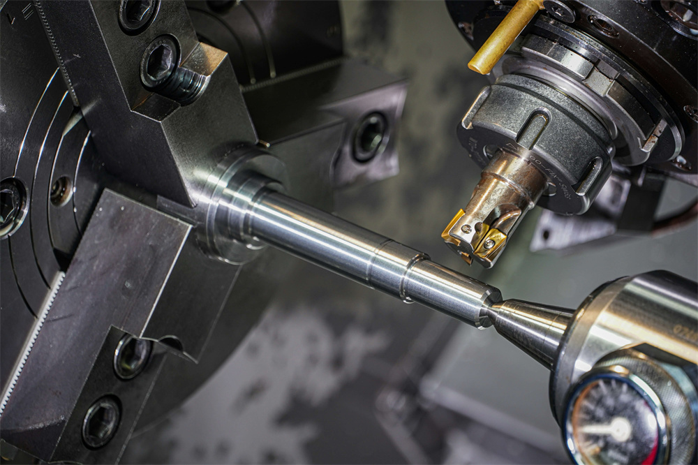
Materials and Finishes
Material selection and surface finish are critical decisions in CNC machining that impact part performance, cost, appearance, and post-production requirements. This section outlines common material choices and finishing options to guide efficient and functional design.
Common CNC Materials
Metal Materials
· Aluminum (6061, 7075, 2024)
Lightweight, corrosion-resistant, and easy to machine. Ideal for aerospace, automotive, and general engineering applications. Anodizes well.
· Steel (1018, 1045, 4140)
Offers excellent strength, toughness, and weldability. Used in mechanical components and structural applications.
· Stainless Steel (304, 316, 303)
Provides high corrosion resistance and durability. Often used in medical, marine, and food-grade parts. 303 is more machinable.
· Brass (C360, C260)
Highly machinable with a smooth finish and natural corrosion resistance. Common in electrical connectors and decorative fittings.
· Titanium (Grade 2, Grade 5)
Known for an excellent strength-to-weight ratio and corrosion resistance. Used in aerospace, medical implants, and motorsports. Requires specialized tooling and slower feeds.
Plastic and Composite Materials
· ABS
Tough and affordable. Commonly used in housings, fixtures, and prototypes.
· POM (Delrin/Acetal)
Low friction, high strength, and excellent dimensional stability. Suitable for gears, bushings, and mechanical parts.
· Nylon
Tough and abrasion-resistant. Often used for structural applications and insulators.
· PTFE (Teflon)
Chemically inert and temperature-resistant. Used in seals and medical components. Difficult to machine due to softness.
· Polycarbonate
Transparent and impact-resistant. Ideal for windows and safety equipment.
· Carbon Fiber Composites & G10
Lightweight and rigid but abrasive on tools. Often used in aerospace, electronics, and high-performance parts. Requires diamond-coated tooling.
Inserts
Inserts are essential for reinforcing threads in plastic or soft-metal parts, especially where repeated assembly/disassembly is expected.
· Heat-Set Inserts: Installed using thermal expansion and pressure. Common in thermoplastics.
· Ultrasonic Inserts: Embedded using vibration, ensuring strong fusion with the host material.
· Press-Fit Inserts: Mechanically pressed into pre-drilled holes. Suitable for metal or hard plastic parts.
· Tip: Clearly define insert type, location, and installation method in your technical drawings.
Part Markings
CNC-machined parts often require identification or traceability. Markings may include part numbers, serial codes, or inspection stamps.
· Laser Engraving: Precise and permanent; suitable for metals and some plastics.
· CNC Engraving: Machined directly into the surface. Depth should be 0.3–0.5 mm for visibility.
· Ink Stamping or Labeling: Less durable, better for temporary or internal-use parts.
Place markings on non-critical surfaces to avoid compromising tolerances or surface finishes.
Surface Finishes
Post-processing treatments enhance function, wear resistance, appearance, and corrosion protection. Choose finishes based on part material, use environment, and cosmetic requirements.
Overview of Common Finishes
| Finish Type | Compatible Materials | Purpose | Notes |
|
Anodizing |
Aluminum |
Adds corrosion resistance and color |
Type II (cosmetic), Type III (hard coat) |
|
Powder Coating |
Most metals |
Durable, decorative coating |
Thick and even, multiple color options |
|
Bead Blasting |
Aluminum, steel, plastics |
Uniform matte surface |
Removes tool marks; not for tight-tolerance areas |
|
Polishing |
Metals, plastics |
Improves appearance, smoothness |
Labor-intensive, enhances aesthetics |
| Finish Type | Compatible Materials | Purpose | Notes |
|
Passivation |
Stainless steel |
Removes surface contaminants |
Enhances corrosion resistance |
|
Black Oxide |
Carbon steels |
Dark finish, mild corrosion protection |
Minimal dimensional change |
|
Electropolishing |
Stainless steel, titanium |
High-purity and smoothness |
Ideal for medical, food-grade, and optical parts |
|
Brushing |
Aluminum, stainless steel |
Creates linear finish texture |
Common for consumer-facing products |
Selecting the Right Finish
Consider these factors when choosing a finish:
· Functionality: Will the part face wear, heat, or chemical exposure?
· Aesthetics: Does the part require a decorative or matte finish?
· Tolerances: Some finishes (e.g., powder coating) add measurable thickness.
· Material: Not all finishes are compatible with every substrate.
Finishes improve appearance, corrosion resistance, and wear properties:
· As-Machined: No additional processing; shows tool marks.
· Anodizing: Adds corrosion resistance and color to aluminum parts.
· Powder Coating: Durable, decorative finish for metal parts.
· Bead Blasting: Creates a uniform matte texture.
· Polishing: Enhances visual appeal and smoothness.
· Passivation: Removes surface contaminants on stainless steel.
Steps to Prepare & Source Your Custom Parts
Successfully sourcing custom CNC machined parts involves a structured workflow, from conceptualization to final inspection. Below is a step-by-step guide to help engineers, designers, and procurement teams navigate the process efficiently.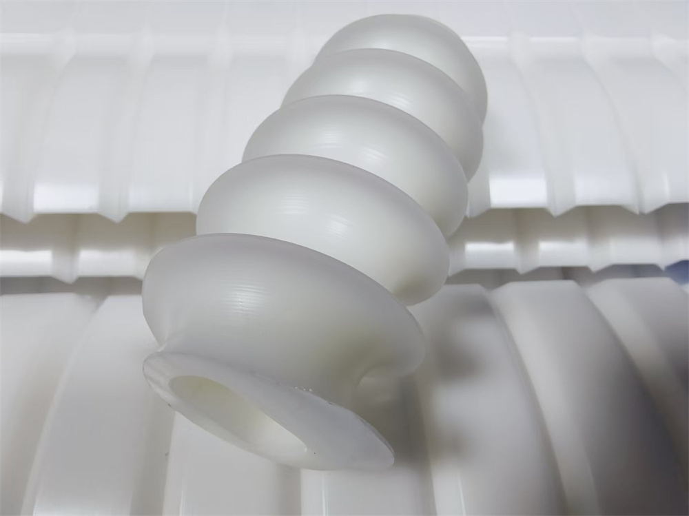
Define Your Requirements
Start with a clear understanding of the functional and technical goals of the part:
· Application and Environment: Is the part structural, cosmetic, or functional? Will it be exposed to heat, chemicals, or load-bearing forces?
· Material Selection:Choose based on strength, machinability, weight, corrosion resistance, or compliance (e.g., FDA, RoHS).
· Tolerance Requirements: Apply tight tolerances only where absolutely necessary. Specify ISO 2768-m or tighter for precision features.
· Surface Finish: Decide whether post-processing (e.g., anodizing, bead blasting) is cosmetic, functional, or both.
· Quantity and Lead Time: Distinguish between prototyping, low-volume, or high-volume production to guide supplier selection and pricing.
Tip:Document all requirements in a technical specification sheet.
Create a 3D CAD Model
Use professional-grade software to generate a solid, parametric model:
· Recommended Software: SolidWorks, Autodesk Fusion 360, Siemens NX, or Creo.
· Model Guidelines:
Remove unnecessary features (e.g., logos, fillets) if not functionally critical.
Ensure no overlapping bodies or non-manifold geometries.
Confirm scale and units (mm/inch).
Export files in universally accepted formats:
· STP / STEP (.stp, .step) – Preferred for manufacturing.
· IGES (.igs) – Legacy systems, less accurate.
· SLDPRT, 3MF, or Parasolid (.x_t) – For advanced features or internal teams.
Prepare a 2D Technical Drawing
Even with a 3D model, 2D drawings remain essential for conveying detailed specifications:
Include:
· Full dimensions (including depth, radius, and critical features)
· Tolerances and datum references
· Hole and thread specifications (e.g., M6 × 1, ¼-20 UNC)
· Surface finish callouts
· GD&T symbols (per ASME Y14.5 or ISO 1101)
· Material and finish requirements
· Quantity and revision number
File format: PDF is standard; make sure it's exportable at high resolution and includes title blocks.
Identify a Suitable Manufacturer
Choose a CNC shop or platform based on your part requirements and business priorities:
Considerations:
· Capabilities: Ensure access to required materials, machinery (3-, 4-, or 5-axis), and finishing options.
· Certifications: ISO 9001, AS9100, or ITAR may be required for certain industries.
· Lead Time: Confirm turnaround for prototyping vs. production runs.
· Communication: Look for transparency, technical support, and responsiveness.
· Location: Domestic vs. international sourcing impacts cost, shipping, and IP control.
Types of Suppliers:
· Local shops for fast turnaround
· Online platforms with brand effect
· Overseas suppliers have cost-effectiveness advantages
Request a Quotation (RFQ)
Submit your 3D model, 2D drawing, and any additional specs to receive accurate quotes.
Information to include:
· Material type and grade
· Quantity and delivery date
· Any certifications or inspections required
· Secondary operations (e.g., anodizing, heat treatment)
· Budgetary constraints (if applicable)
Response time: Most suppliers reply within 24–72 hours. Online platforms often provide instant or AI-assisted quoting.
Tip: Compare multiple quotes and ask for a Design for Manufacturability (DFM) review before committing.
Prototype (If Needed)
Before scaling up, run a low-volume prototype batch to validate:
· Fit and Assembly: Ensure integration with mating components.
· Functionality: Test load-bearing, movement, sealing, etc.
· Aesthetics: Assess finish quality and branding.
· Tolerances: Check against drawings and CAD model.
Options: Start with a CNC prototype, or use 3D printing to assess general geometry if full mechanical properties are not immediately needed.
Place the Order
Once satisfied with the quote and prototype:
· Finalize the CAD and drawing revisions
· Sign off on manufacturing agreement and NDA (if needed)
· Specify quality checks or First Article Inspection (FAI)
· Confirm production timeline and delivery method
Use a PO system or platform dashboard to track progress.
Quality Control and Delivery Inspection
Upon delivery, inspect parts according to your QA checklist:
· Dimensional Inspection: Use calipers, CMMs, or gauges.
· Finish Review: Check coating consistency, color, and uniformity.
· Thread and Fit Tests: Use go/no-go gauges or manual tools.
· Functional Testing: Perform mechanical or electrical tests as applicable.
Documentation to request:
· Certificate of Conformance (CoC)
· Material certifications (e.g., mill certs)
· Surface finish or heat treatment reports
· Inspection reports
Document any issues and notify the supplier promptly to initiate resolution or remanufacture.
Suggestions to Reduce the Machining Cost
CNC machining offers precision and versatility, but costs can escalate due to complex geometries, tight tolerances, and specialized requirements. By applying smart design and sourcing strategies, you can significantly reduce manufacturing expenses without compromising quality.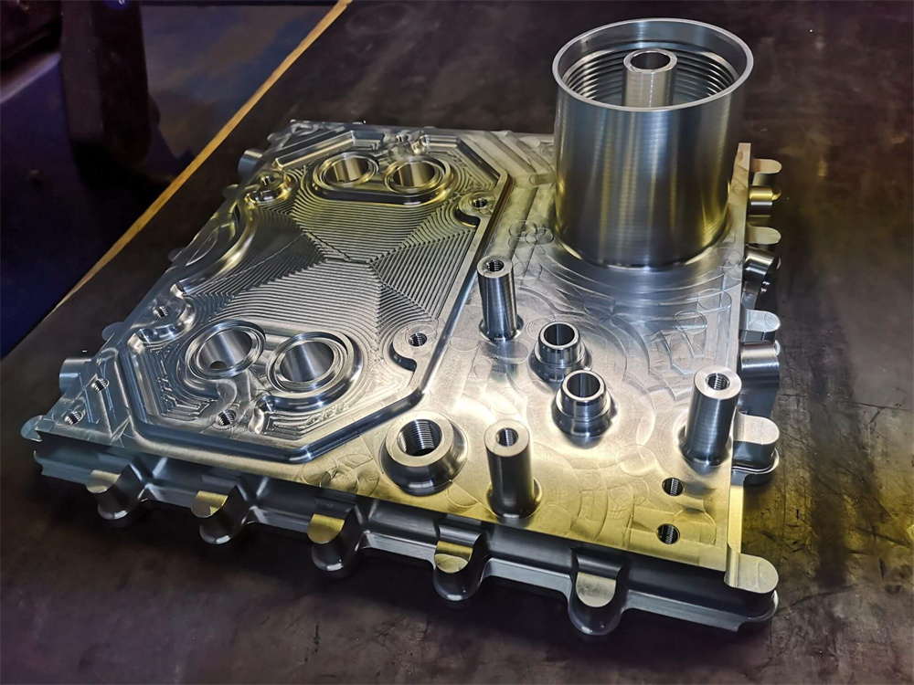
Simplify the Part Design
Complex parts often require multiple setups, custom tooling, or 5-axis machining—all of which increase costs. Whenever possible:
· Eliminate unnecessary features (e.g., decorative grooves, tight internal corners)
· Use symmetrical designs that simplify fixturing
· Avoid part geometries that require repositioning during machining
Tip: Design for 3-axis machining unless absolutely necessary to use 4- or 5-axis capabilities.
Use Standard Features and Dimensions
Align your design with industry-standard tooling to reduce programming and machining time:
· Select hole diameters compatible with standard drill sizes (e.g., 3, 6, 8, 10 mm)
· Use standard thread types (e.g., M6, ¼-20 UNC) and depths
· Apply standard corner radii that match common end mill sizes (e.g., 3 mm or 6 mm)
Result: Fewer tool changes, faster production cycles, and lower tool wear.
Avoid Extremely Tight Tolerances
Unnecessarily tight tolerances can double or triple the machining cost due to slower speeds, increased scrap risk, and additional inspection:
· Use ISO 2768-m or -f for non-critical features
· Reserve ±0.01 mm tolerances only for interfacing parts or precision fits
· Clearly label which dimensions are critical-to-function (CTF) in the drawing
Tip: When in doubt, consult the manufacturer during the design phase for DFM feedback.
Minimize Deep Cavities and Thin Walls
Deep pockets require longer tool reach, leading to deflection and vibration issues. Thin walls can flex under machining loads, resulting in poor surface finishes or dimensional errors.
Recommended Guidelines:
· Depth-to-width ratio < 4:1 for end mills
· Wall thickness > 1 mm for metals; > 1.5 mm for plastics
· Avoid unsupported or cantilevered structures
Where deep pockets are necessary, consider roughing with large tools and finishing with smaller tools to reduce time.
Choose Cost-Effective Materials
Material costs and machinability vary widely:
· Aluminum 6061: Excellent machinability and widely available
· Mild Steel: Cost-effective for structural parts
· Plastics (e.g., ABS, Delrin): Fast to machine, ideal for non-load-bearing components
Avoid exotic materials (e.g., Inconel, hardened steels, PEEK) unless absolutely required—they are slower to machine and consume more tooling.
Reduce Setup Time
Parts that require multiple operations or complex fixturing increase labor time:
· Design flat or prismatic features for easy clamping
· Add locating holes or features that simplify re-orientation
· Consolidate multiple small parts into a single large plate to reduce fixture changes
Pro tip: Design parts that can be machined in one setup to save time and reduce error risks.
Avoid Small or Intricate Text
Text, logos, or serial numbers add programming time and require small cutting tools. For non-functional branding:
· Use larger fonts (≥12 pt) with simple geometry
· Keep engraving depth shallow (0.3–0.5 mm)
· Choose sans-serif fonts and avoid cursive or overly decorative styles
Laser marking can be more efficient and cost-effective than CNC engraving for larger batches.
Plan for Batch Production
Economies of scale can significantly reduce per-unit cost:
· Batching reduces machine setup time
· Allows for tooling amortization across more units
· Enables automation and less manual intervention
Tip: Even a small volume increase (from 1 to 10 units) can lead to meaningful savings.
Limit Custom Finishes
Post-processing steps add time and cost. If cosmetic appearance isn't critical:
· Skip anodizing or polishing unless required for corrosion resistance or aesthetics
· Consider bead blasting instead of mirror polishing
· Choose standard color coatings if appearance is a concern
Simpler finishes are faster, cheaper, and easier to inspect.
Collaborate Early with Your Manufacturer
Design for Manufacturability (DFM) input from your CNC supplier can uncover savings before production:
· Send initial designs for feedback during the quoting phase
· Ask about tool access, fixturing options, and material recommendations
· Leverage their experience in optimizing part geometry or combining multiple parts
This partnership often results in better part performance and lower overall cost.
Summary of Cost-Saving Techniques
| Strategy | Impact |
| Simplify geometry | Reduces machining time and errors |
| Use standard dimensions | Enables faster, cheaper tooling |
| Relax tolerances | Avoids over-engineering and inspection overhead |
| Avoid deep features | Minimizes tool deflection and fixturing complexity |
| Select common materials | Saves on raw cost and tooling wear |
| Minimize setups | Improves efficiency and alignment accuracy |
| Limit intricate text | Avoids specialized tooling and longer cycles |
| Increase order quantity | Reduces unit cost through batching |
| Skip custom finishes | Cuts down on post-processing time |
| Get DFM feedback early | Prevents rework and ensures feasibility |
By understanding the principles, limitations, and best practices of CNC machining, engineers and designers can create optimized parts that are both functional and cost-effective. With proper planning and collaboration with experienced manufacturers, custom CNC parts can be produced efficiently and reliably.


 sophia@alcrocn.com
 +86 15338350382
 6th North Street, Xiagang Community, Chang'an Town, Dongguan City, Guangdong Province, China.
